Saturday, March 18, 2017

Automobile Technology: CRDI (Common Rail Direct Injection)

Automobile Technology: CRDI (Common Rail Direct Injection):    

CRDI (Common Rail Direct Injection)


     CRDi stands for Common Rail
Direct Injection meaning, direct injection of the fuel into the
cylinders of a diesel engine via a single, common line, called the
common rail which is connected to all the fuel injectors.

   
 Whereas ordinary diesel direct fuel-injection systems have to build up
pressure anew for each and every injection cycle, the new common rail
(line) engines maintain constant pressure regardless of the injection
sequence. This pressure then remains permanently available throughout
the fuel line. The engine's electronic timing regulates injection
pressure according to engine speed and load. The electronic control unit
(ECU) modifies injection pressure precisely and as needed, based on
data obtained from sensors on the cam and crankshafts. In other words,
compression and injection occur independently of each other. This
technique allows fuel to be injected as needed, saving fuel and lowering
emissions.

     More accurately measured and timed mixture spray
in the combustion chamber significantly reducing unburned fuel gives
CRDi the potential to meet future emission guidelines such as Euro V.
CRDi engines are now being used in almost all Mercedes-Benz, Toyota,
Hyundai, Ford and many other diesel automobiles.


History


     The common rail system
prototype was developed in the late 1960s by Robert Huber of Switzerland
and the technology further developed by Dr. Marco Ganser at the Swiss
Federal Institute of Technology in Zurich, later of Ganser-Hydromag AG
(est.1995) in Oberägeri. The first successful usage in a production
vehicle began in Japan by the mid-1990s. Modern common rail systems,
whilst working on the same principle, are governed by an engine control
unit (ECU) which opens each injector electronically rather than
mechanically. This was extensively prototyped in the 1990s with
collaboration between Magneti Marelli, Centro Ricerche Fiat and Elasis.
The first passenger car that used the common rail system was the 1997
model Alfa Romeo 156 2.4 JTD, and later on that same year Mercedes-Benz C
220 CDI.

     Common rail engines have been used in marine and
locomotive applications for some time. The Cooper-Bessemer GN-8 (circa
1942) is an example of a hydraulically operated common rail diesel
engine, also known as a modified common rail. Vickers used common rail
systems in submarine engines circa 1916. Early engines had a pair of
timing cams, one for ahead running and one for astern. Later engines had
two injectors per cylinder, and the final series of constant-pressure
turbocharged engines were fitted with four injectors per cylinder. This
system was used for the injection of both diesel oil and heavy fuel oil
(600cSt heated to a temperature of approximately 130 °C). The common
rail system is suitable for all types of road cars with diesel engines,
ranging from city cars such as the Fiat Nuova Panda to executive cars
such as the Audi A6.


Operating Principle


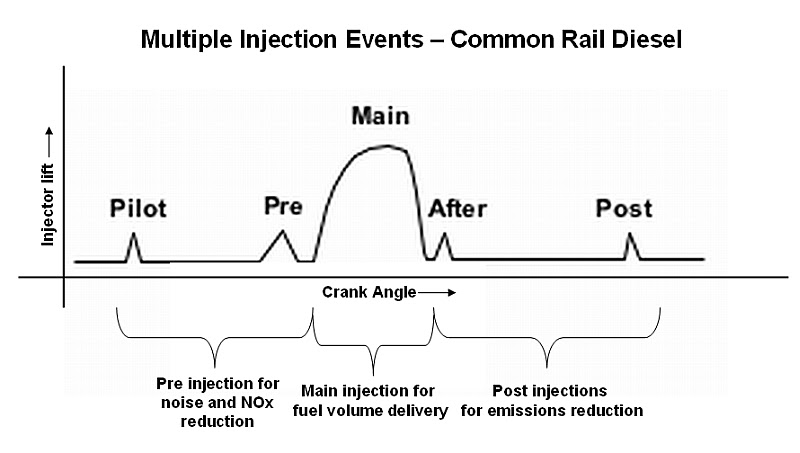
     Solenoid or piezoelectric
valves make possible fine electronic control over the fuel injection
time and quantity, and the higher pressure that the common rail
technology makes available provides better fuel atomisation. In order to
lower engine noise, the engine's electronic control unit can inject a
small amount of diesel just before the main injection event ("pilot"
injection), thus reducing its explosiveness and vibration, as well as
optimizing injection timing and quantity for variations in fuel quality,
cold starting and so on. Some advanced common rail fuel systems perform
as many as five injections per stroke.

     Common rail engines
require very short (< 10 second) or no heating-up time at all ,
dependent on ambient temperature, and produce lower engine noise and
emissions than older systems. Diesel engines have historically used
various forms of fuel injection. Two common types include the unit
injection system and the distributor/inline pump systems (See diesel
engine and unit injector for more information). While these older
systems provided accurate fuel quantity and injection timing control,
they were limited by several factors:

• They were cam driven, and
injection pressure was proportional to engine speed. This typically
meant that the highest injection pressure could only be achieved at the
highest engine speed and the maximum achievable injection pressure
decreased as engine speed decreased. This relationship is true with all
pumps, even those used on common rail systems; with the unit or
distributor systems, however, the injection pressure is tied to the
instantaneous pressure of a single pumping event with no accumulator,
and thus the relationship is more prominent and troublesome.


They were limited in the number and timing of injection events that
could be commanded during a single combustion event. While multiple
injection events are possible with these older systems, it is much more
difficult and costly to achieve.


• For the typical
distributor/inline system, the start of injection occurred at a
pre-determined pressure (often referred to as: pop pressure) and ended
at a pre-determined pressure. This characteristic resulted from "dummy"
injectors in the cylinder head which opened and closed at pressures
determined by the spring preload applied to the plunger in the injector.
Once the pressure in the injector reached a pre-determined level, the
plunger would lift and injection would start.


     In common rail systems, a high-pressure pump stores a
reservoir of fuel at high pressure — up to and above 2,000 bars (psi).
The term "common rail" refers to the fact that all of the fuel injectors
are supplied by a common fuel rail which is nothing more than a
pressure accumulator where the fuel is stored at high pressure. This
accumulator supplies multiple fuel injectors with high-pressure fuel.
This simplifies the purpose of the high-pressure pump in that it only
has to maintain a commanded pressure at a target (either mechanically or
electronically controlled). The fuel injectors are typically
ECU-controlled. When the fuel injectors are electrically activated, a
hydraulic valve (consisting of a nozzle and plunger) is mechanically or
hydraulically opened and fuel is sprayed into the cylinders at the
desired pressure. Since the fuel pressure energy is stored remotely and
the injectors are electrically actuated, the injection pressure at the
start and end of injection is very near the pressure in the accumulator
(rail), thus producing a square injection rate. If the accumulator, pump
and plumbing are sized properly, the injection pressure and rate will
be the same for each of the multiple injection events.


Advantages & Disadvantages


Advantages


   CRDi engines are advantageous in many ways. Cars fitted with this
new engine technology are believed to deliver 25% more power and torque
than the normal direct injection engine. It also offers superior pick
up, lower levels of noise and vibration, higher mileage, lower
emissions, lower fuel consumption, and improved performance.

     In India, diesel is cheaper than petrol and this fact adds to the credibility of the common rail direct injection system.


Disadvantages

     Like all good things have a
negative side, this engine also have few disadvantages. The key
disadvantage of the CRDi engine is that it is costly than the
conventional engine. The list also includes high degree of engine
maintenance and costly spare parts. Also this technology can’t be
employed to ordinary engines.


Applications


     The most common
applications of common rail engines are marine and locomotive
applications. Also, in the present day they are widely used in a variety
of car models ranging from city cars to premium executive cars.


   Some of the Indian car manufacturers who have widely accepted the
use of common rail diesel engine in their respective car models are the
Hyundai Motors, Maruti Suzuki, Fiat, General Motors, Honda Motors, and
the Skoda. In the list of luxury car manufacturers, the Mercedes-Benz
and BMW have also adopted this advanced engine technology. All the car
manufacturers have given their own unique names to the common CRDi
engine system.

     However, most of the car manufacturers have
started using the new engine concept and are appreciating the long term
benefits of the same. The technology that has revolutionized the diesel
engine market is now gaining prominence in the global car industry.

     CRDi technology revolutionized diesel engines and also petrol engines (by introduction of GDI technology).

   By introduction of CRDi a lot of advantages are obtained, some of
them are, more power is developed, increased fuel efficiency, reduced
noise, more stability, pollutants are reduced, particulates of exhaust
are reduced, exhaust gas recirculation is enhanced, precise injection
timing is obtained, pilot and post injection increase the combustion
quality, more pulverization of fuel is obtained, very high injection
pressure can be achieved, the powerful microcomputer make the whole
system more perfect, it doubles the torque at lower engine speeds. The
main disadvantage is that this technology increase the cost of the
engine. Also this technology can’t be employed to ordinary engines.

Autoelex Blog: Engine Combustion - Compression Ignition (Diesel)

Autoelex Blog: Engine Combustion - Compression Ignition (Diesel):

Engine Combustion - Compression Ignition (Diesel)


In
a diesel or compression ignition engine, the first and major difference
compared to a spark ignition engine is the way that fuel and air is
prepared for combustion, also, the way combustion is initiated. 


Diesel engines
induce air only during the intake stroke - the air charge is compressed
in the cylinder, heating it accordingly, the final temperature at the
end of the compression stroke is above the self ignition temperature of
the fuel and this factor is essential, as this initiates the combustion
event when the fuel meets with the hot air. The advantage of compressing
air only is that we don't have to consider self ignition of any
fuel/air during compression (as per gasoline engine) as at this point in
the engine cycle, there is no fuel to burn! The combustion process is
quite different to the gasoline engine, the timing and rate of
combustion is controlled via the introduction of fuel into the cylinder
(via the fuel injection system). The combustion process itself takes
place at the interface between the fuel and air. Therefore, sufficient
air motion in the cylinder (generally swirl in a diesel engine) is
essential to sweep away the products of combustion, ensuring that the
fuel charge always has sufficient oxygen at the flame interface to
prevent to formation of soot due to localised oxygen starvation. 

Fig 1 - Air motion in a diesel engine is generally 'swirl'

The overall
volume of the combustion chamber itself has a variable air/fuel ratio
during operation, that is only chemically correct at the fuel to air
interface. In most operating conditions, the average air/fuel ratio in
the cylinder is considerably weak (compared to stoichiometric). The
engine power output is controlled by the amount of fuel injected, so
no throttling is needed and this improves efficiency at part load due to
the lack of pumping losses associated with restricting the airflow into
the engine. The technical term associated with diesel type combustion
is ‘diffusion’ combustion, as the fuel burning takes place at the
interface where fuel diffuses into the air, and vice-versa. 
Due to the fact
that fuel and air have to be mixed during the compression/expansion
cycle (as opposed to pre-mixed, outside the cylinder) this reduces the
amount of time available to complete the whole mixing and combustion
process. Hence, generally speaking, diesel engines cannot rev as highly
as gasoline engine. Therefore, to get more power from a diesel engine
you increase the torque by turbocharging it! - common practice these
days. It’s notable though that the diesel engine combustion cycle, and
engine itself, is more efficient than gasoline for several reasons - the
higher compression ratio increases the cycle efficiency, the lack of a
throttle reduces pumping losses and the high precision, metered
injection system reduces cylinder-to-cylinder variation.


Fig 2 - A common rail diesel fuel injection (FIE) system


Diesel engines
have undergone considerable development over the last few years, mainly
in the area of fuel injection system technology. These developments have
enabled sophisticated, electronically controlled injection systems,
that can help reduce particulate emissions as well a engine noise
emissions. I think that anybody would agree that travelling in a modern
diesel engine car is no longer a noisy or unpleasant experience. Modern
diesels are very refined and smooth in operation!


Fig 3 - Direct and Indirect fuel injection - direct injection is predominant now!


All modern
diesel engines for passenger cars use direct injection technology (as
opposed to indirect). In the past, indirect injection - injecting fuel
into a pre-chamber - was technology used to create the required air
charge motion to speed up the combustion event, thus increasing the
maximum possible engine speed and power density. However, the increased
surface area of the combustion and pre-chamber increases heat losses and
reduces efficiency and has now been completely superseded by direct
injection systems for most applications. In a modern diesel engine, the
fuel injector nozzle sprays a complex, engineered spray pattern into the
hot , highly turbulent combustion chamber gases, to initiate the
combustion event at around TDC.  The fuel is injected radially into the
combustion chamber, the liquid fuel vaporises and mixes with the air as
it travels away from the injector tip nozzles. The fuel self-ignites at
multiple ignition sites along each of the injection sprays. 


Fig 4 - Diesel spray pattern and combustion from a thermal image system


The design of
the combustion chamber, in the piston bowl, is critical to the
efficiency of the combustion event. This design creates the necessary
motion and energy in the cylinder charge to make sure that each tiny
droplet of fuel has sufficient oxygen for complete combustion, right
throughout the injection period. 


Fig 5 - The 3 phases of diesel combustion

The initial
combustion takes a certain time period to establish, known as the delay
time, then the fuel will auto-ignite creating a very rapid energy
release and the flame spreads rapidly through the fuel that is exposed
to sufficient air for combustion. This creates a rapid rise in cylinder
pressure, forcing the piston down the cylinder. As the power (or
expansion) stroke continues, further mixing of fuel and air occurs,
accompanied by further, more controlled combustion period where energy
release is controlled by injection rate. Note that it is the rapid
release of energy, after the delay period, which causes the
characteristic combustion ‘knock’ associated with diesel engine.


Fig 6 - Common rail, electronic diesel systems allow multiple injection events with better control of the combustion process

Modern,
electronic fuel injection systems, with multiple injection events,
effectively reduce this noise via a more gradual introduction of the
fuel into the cylinder (via pre-injection events) as opposed to a
single-shot event, where all fuel is injected at once (causing rapid
pressure rise and noise). Note that single-shot injection strategies
were all that was possible with a simple rotary or in-line injector pump
in the past. In summary, the key points to consider with respect to the
compression ignition engine are:
  • The fuel/air mixture is prepared internally in the cylinder, during the engine cycle and relies on self ignition
  • The engine power is controlled via the quantity of fuel injected in each engine cycle. 
  • The
    compression ratio is not limited by the fuel as the compressed charge is
    just air, It is only limited by the strength of the engine design as
    peak cylinder pressures are very high
  • In operation, engine maximum torque is limited by peak pressures/mechanical loading
  • Rapid pressure rise, generated by the self-ignition of the fuel, creates the diesel engine noise

Aircraft systems: Fuel-Injection Systems

Fuel-Injection Systems:

Fuel-Injection Systems


The
fuel-injection system has many advantages over a conventional carburetor
system. There is less danger of induction system icing, since the drop
in temperature due to fuel vaporization takes place in or near the
cylinder. Acceleration is also improved because of the positive action
of the injection system. In addition, fuel injection improves fuel
distribution. This reduces the overheating of individual cylinders often
caused by variation in mixture due to uneven distribution. The
fuel-injection system also gives better fuel economy than a system in
which the mixture to most cylinders must be richer than necessary so
that the cylinder with the leanest mixture operates properly.

Fuel-injection
systems vary in their details of construction, arrangement, and
operation. The Bendix and Continental fuel-injection systems are
discussed in this section. They are described to provide an
understanding of the operating principles involved. 

Bendix/Precision Fuel-Injection System

The Bendix
inline stem-type regulator injection system (RSA) series consists of an
injector, flow divider, and fuel discharge nozzle. It is a
continuous-flow system which measures engine air consumption and uses
airflow forces to control fuel flow to the engine. The fuel distribution
system to the individual cylinders is obtained by the use of a fuel
flow divider and air bleed nozzles.

Fuel Injector

The fuel injector assembly consists of:
  1. An airflow section,
  2. A regulator section, and
  3. A fuel metering section. Some fuel injectors are equipped with an automatic mixture control unit.
Airflow Section
Figure 1

The airflow consumption of the engine is measured by sensing impact pressure and venturi throat pressure in the throttle
body. These pressures are vented to the two sides of an air diaphragm. A
cutaway view of the airflow measuring section is shown in Figure 1.
Movement of the throttle valve causes a change in engine air
consumption. This results in a change in the air velocity in the
venturi. When airflow through the engine increases, the pressure on the
left of the diaphragm is lowered due to the drop in pressure at the
venturi throat. 
[Figure
2] As a result, the diaphragm moves to the left, opening the ball
valve. Contributing to this force is the impact pressure that is picked
up by the impact tubes. 
Figure 2
Figure 3
[Figure 3] This
pressure differential is referred to as the “air metering force.” This
force is accomplished by channeling the impact and venturi suction
pressures to opposite sides of a diaphragm. The difference between these
two pressures becomes a usable force that is equal to the area of the
diaphragm times the pressure difference.

Regulator Section

The regulator
section consists of a fuel diaphragm that opposes the air metering
force. Fuel inlet pressure is applied to one side of the fuel diaphragm
and metered fuel pressure is applied to the other side. The differential
pressure across the fuel diaphragm is called the fuel metering force.
The fuel pressure shown on the ball side of the fuel diaphragm is the
pressure after the fuel has passed through the fuel strainer and the
manual mixture control rotary plate and is referred to as metered fuel
pressure. Fuel inlet pressure is applied to the opposite side of the
fuel diaphragm. The ball valve attached to the fuel diaphragm controls
the orifice opening and fuel flow through the forces placed on it.
[Figure 4]
Figure 4

The distance
the ball valve opens is determined by the difference between the
pressures acting on the diaphragms. This difference in pressure is
proportional to the airflow through the injector. Thus, the volume of
airflow determines the rate of fuel flow.

Under low power
settings, the difference in pressure created by the venturi is
insufficient to accomplish consistent regulation of the fuel. A
constant-head idle spring is incorporated to provide a constant fuel
differential pressure. This allows an adequate final flow in the idle
range.

Fuel Metering Section
Figure 5
The fuel
metering section is attached to the air metering section and contains an
inlet fuel strainer, a manual mixture control valve, an idle valve, and
the main metering jet. [Figure 5] The idle valve is connected to the
throttle valve by means of an external adjustable link. In some injector
models, a power enrichment jet is also located in this section.
Figure 6

The purpose of
the fuel metering section is to meter and control the fuel flow to the
flow divider. [Figure 6] The manual mixture control valve produces full
rich condition when the lever is against the rich stop, and a
progressively leaner mixture as the lever is moved toward idle cutoff.
Both idle speed and idle mixture may be adjusted externally to meet
individual engine requirements.

Flow Divider


The metered
fuel is delivered from the fuel control unit to a pressurized flow
divider. This unit keeps metered fuel under pressure, divides fuel to
the various cylinders at all engine 
speeds, and shuts off the individual nozzle lines when the control is placed in idle cutoff.
Figure 7
Referring to
the diagram in Figure 7, metered fuel pressure enters the flow divider
through a channel that permits fuel to pass through the inside diameter
of the flow divider needle. At idle speed, the fuel pressure from the
regulator must build up to overcome the spring force applied to the
diaphragm and valve assembly. This moves the valve upward until fuel can
pass out through the annulus of the valve to the fuel nozzle. [Figure
8] Since the regulator meters and delivers a fixed amount of fuel to the
flow divider, the valve opens only as far as necessary to pass this
amount to the nozzles. At idle, 
the opening required is very small; the fuel for the individual cylinders is divided at idle by the flow divider.
Figure 8

As fuel flow
through the regulator is increased above idle requirements, fuel
pressure builds up in the nozzle lines. This pressure fully opens the
flow divider valve, and fuel distribution to the engine becomes a
function of the discharge nozzles.

A fuel pressure
gauge, calibrated in pounds per hour fuel flow, can be used as a fuel
flow meter with the Bendix RSA injection system. This gauge is connected
to the flow divider and senses the pressure being applied to the
discharge nozzle. This pressure is in direct proportion to the fuel flow
and indicates the engine power output and fuel consumption.

Fuel Discharge Nozzles
Figure 9

The fuel
discharge nozzles are of the air bleed configuration. There is one
nozzle for each cylinder located in the cylinder head. [Figure 9] The
nozzle outlet is directed into the intake port. Each nozzle incorporates
a calibrated jet. The jet size is determined by the available fuel
inlet pressure and the maximum fuel flow required by the engine. The
fuel is discharged through this jet into an ambient air pressure chamber
within the nozzle assembly. Before entering the individual intake valve
chambers, the fuel is mixed with air to aid in atomizing the fuel. Fuel
pressure, before the individual nozzles, is in direct proportion to
fuel flow; therefore, a simple pressure gauge can be calibrated in fuel
flow in gallons per

hour and be
employed as a flowmeter. Engines modified with turbosuperchargers must
use shrouded nozzles. By the use of an air manifold, these nozzles are
vented to the injector air inlet pressure.

Continental/TCM Fuel-Injection System

The Continental
fuel-injection system injects fuel into the intake valve port in each
cylinder head. [Figure 10] The system consists of a fuel injector pump, a
control unit, a fuel manifold, and a fuel discharge nozzle. It is a
continuous-flow type, which controls fuel flow to match engine airflow.
The continuous-flow system permits the use of a rotary vane pump which
does not require timing to the engine.
Figure 10

Fuel-Injection Pump
Figure 11

The fuel pump
is a positive-displacement, rotary-vane type with a splined shaft for
connection to the accessory drive system of the engine. [Figure 11] A
spring-loaded, diaphragm-type relief valve is provided. The relief valve
diaphragm chamber is vented to atmospheric pressure. A sectional view
of a fuel-injection pump is shown in Figure 12.

Fuel enters at
the swirl well of the vapor separator. Here, vapor is separated by a
swirling motion so that only liquid fuel is delivered to the pump. The
vapor is drawn from the top center of the swirl well by a small pressure
jet of fuel and is directed into the vapor return line. This line
carries the vapor back to the fuel tank.
Figure 12

Ignoring the
effect of altitude or ambient air conditions, the use of a
positive-displacement, engine-driven pump means that changes in engine
speed affect total pump flow proportionally. Since the pump provides
greater capacity than is required by the engine, a recirculation path is
required. By arranging a calibrated orifice and relief valve in this
path, the pump delivery pressure is also maintained in proportion to
engine speed. These provisions assure proper pump pressure and fuel
delivery for all engine operating speeds.

A check valve
is provided so that boost pump pressure to the system can bypass the
engine-driven pump for starting. This feature also suppresses vapor
formation under high ambient temperatures of the fuel, and permits use
of the auxiliary pump as a source of fuel pressure in the event of
engine-driven pump failure.

Fuel/Air Control Unit
Figure 13

The function of
the fuel/air control assembly is to control engine air intake and to
set the metered fuel pressure for proper fuel/air ratio. The air
throttle is mounted at the manifold inlet and its butterfly valve,
positioned by the throttle control in the aircraft, controls the flow of
air to the engine. [Figure 13]

The air
throttle assembly is an aluminum casting which contains the shaft and
butterfly-valve assembly. The casting bore size is tailored to the
engine size, and no venturi or other restriction is used.

Fuel Control Assembly

The fuel
control body is made of bronze for best bearing action with the
stainless steel valves. Its central bore contains a metering valve at
one end and a mixture control valve at the other end. Each stainless
steel rotary valve includes a groove which forms a fuel chamber.

Fuel enters the
control unit through a strainer and passes to the metering valve.
[Figure 14] This rotary valve has a cam-shaped edge on the outer part of
the end face. The position of the cam at the fuel delivery port
controls the fuel passed to the manifold valve and the nozzles. The fuel
return port connects to the return passage of the center metering plug.
The alignment of the mixture control valve with this passage determines
the amount of fuel returned to the fuel pump.
Figure 14
By connecting
the metering valve to the air throttle, the fuel flow is properly
proportioned to airflow for the correct fuel/ air ratio. A control level
is mounted on the mixture control valve shaft and connected to the
cockpit mixture control.

Fuel Manifold Valve

The fuel
manifold valve contains a fuel inlet, a diaphragm chamber, and outlet
ports for the lines to the individual nozzles. [Figure 15] The
spring-loaded diaphragm operates a valve in the central bore of the
body. Fuel pressure provides the force for moving the diaphragm. The
diaphragm is enclosed by a cover that retains the diaphragm loading
spring. When the valve is down against the lapped seat in the body, the
fuel lines to the cylinders are closed off. The valve is drilled for
passage of fuel from the diaphragm chamber to its base, and a ball valve
is installed within the valve. All incoming fuel must pass through a
fine screen installed in the diaphragm chamber.
Figure 15
From the fuel-injection control valve, fuel is delivered to the fuel manifold valve, which provides a central point for

dividing fuel
flow to the individual cylinders. In the fuel manifold valve, a
diaphragm raises or lowers a plunger valve to open or close the
individual cylinder fuel supply ports simultaneously.

Fuel Discharge Nozzle

The fuel
discharge nozzle is located in the cylinder head with its outlet
directed into the intake port. The nozzle body contains a drilled
central passage with a counterbore at each end. [Figure 16] The lower
end is used as a chamber for fuel/air mixing before the spray leaves the
nozzle. The upper bore contains a removable orifice for calibrating the
nozzles. Nozzles are calibrated in several ranges, and all nozzles
furnished for one engine are of the same range and are identified by a
letter stamped on the hex of the nozzle body.
Figure 16
Drilled radial
holes connect the upper counterbore with the outside of the nozzle body.
These holes enter the counterbore above the orifice and draw air
through a cylindrical screen fitted over the nozzle body. A shield is
press-fitted on the nozzle body and extends over the greater part of the
filter screen, leaving an opening near the bottom. This provides both
mechanical protection and an abrupt change in the direction of airflow
which keeps dirt and foreign material out of the nozzle interior.

Wednesday, March 1, 2017

When To Replace A Fuel Injector


When To Replace A Fuel Injector

During its evolution, the fuel injector has moved from the intake manifold to the combustion chamber. This has made them more precise in dispensing fuel. If this precision is thrown off by restrictions, electrical problems or fuel problems, it can cause driveability issues.


Here are 10 signs to look for when you need to replace a fuel injector or it needs service.


1. Restrictions

A restriction of only 8% to 10% in a single fuel injector can lean out the fuel mixture and cause a misfire. When this occurs, unburned oxygen enters the exhaust and makes the O2 sensor read lean. On older multiport systems that fire the injectors simultaneously, the computer compensates by increasing the “on” time of all the injectors, which can create an overly rich fuel condition in the other cylinders.

Direct fuel injectors are more sensitive to restrictions because of the precise amount of fuel they inject into the combustion chamber.


2. Turbo Troubles

In turbocharged engines, dirty injectors can have a dangerous leaning effect that may lead to engine-damaging detonation. When the engine is under boost and at a higher rpm, it needs all the fuel the injectors can deliver. If the injectors are dirty and can’t keep up with the engine’s demands, the fuel mixture will lean out, causing detonation to occur. The leaning out may cause higher than normal exhaust temperatures and turbo failure.


3. Heat Soak

When the engine is shut off, the injectors undergo heat soak. Fuel residue evaporates in the injector nozzles, leaving the waxy olefins behind. Because the engine is off, there is no cooling airflow moving through the ports and no fuel flowing through the injectors to wash it away, so heat bakes the olefins into hard varnish deposits. Over time, these deposits can build up and clog the injectors. Even if a vehicle has low mileage, short drive cycles and increased heat soaks can clog the injector.

Since the formation of these deposits is a normal consequence of engine operation, detergents are added to gasoline to help keep the injectors clean. But if a vehicle is used primarily for short-trip driving, the deposits may build up faster than the detergents can wash them away. On four-cylinder engines, the No. 2 and No. 3 injectors are in the hottest location and tend to clog up faster than the end injectors on cylinders No. 1 and No. 4. The same applies to the injectors in the middle cylinders in six- and eight-cylinder engines. The hotter the location, the more vulnerable the injector is to clogging from heat soaks. Throttle body injectors are less vulnerable to heat soak because of their location high above the intake manifold plenum.

Heat soak can affect direct-injection injectors due to their placement in the head. Even with the higher pressures, the orifices can become clogged over time.


4. Increase or Decrease in Long- and Short-Term Fuel Trims

The fuel calibration curves in the Powertrain Control Module (PCM) are based on OEM dyno testing using a new engine. Fuel pressure is within a specified range for that engine, and the injectors are all clean and new. The PCM’s built-in adaptive fuel control strategies allow it to adjust both short-term and long-term fuel trim to compensate for variances in fuel pressure and fuel delivery to maintain the correct air/fuel ratio — but only within certain limits.

The PCM may not be able to increase injector duration enough to offset the difference if:

• An injector becomes clogged with fuel varnish deposits and fails to deliver its normal dose of fuel when it’s energized, or

• Fuel pressure to the injector drops below specifications because of a weak fuel pump, plugged fuel filter or leaky fuel pressure regulator.

This can leave the air/fuel mixture too lean, causing the cylinder to misfire.


5. Not Enough Resistance

The solenoid at the top of the injector creates a magnetic field that pulls up the injector pintle when the injector is energized. The magnetic field must be strong enough to overcome the spring pressure and fuel pressure above the pintle, otherwise the injector may not open all the way. Shorts, opens or excessive resistance in the injector solenoid can also cause problems.

Typically, the solenoids often short internally when injectors fail, which causes a drop in resistance. If the specification calls for 3 ohms, for example, and an injector measures only 1 ohm, it will pull more current than the other injectors. Too much current flow to an injector may cause the PCM injector driver circuit to shut down, killing any other injectors that also share that same driver circuit. One way to check the injectors is with an ohmmeter.


6. Longer Crank Times

An injector leak will cause the rail to lose pressure while the vehicle is sitting resulting in a longer than normal crank because the rail will need extra time to pressurize.


A normal crank time in a diesel common-rail injection system is usually around three to five seconds. This is how long it will take the common-rail pump to build fuel pressure to the “threshold.” The fuel rail pressure threshold for cranking occurs around 5,000 psi. Normal common-rail systems will operate at 5,000 psi at idle and can reach up to 30,000 psi at wide open throttle.


7. Failed Balance Tests

If you suspect that an injector is clogged or malfunctioning, an injector balance test can isolate the bad injector. Scan tools that can disable injectors can isolate an injector for diagnostics. Engine rpm drop may not be an effective diagnostic method when performing a cylinder balance test where an injector is disabled.


A more effective method is looking at the voltage changes from the O2 sensor. Leaking injectors and some dead injectors can be missed even when an injector is disabled. Other problems with the ignition system and mechanical components also may not show an rpm loss when an injector is turned off. If an injector is good, the voltage from the O2 sensor will drop to or below 100mV. If the problem is a closed or dead injector, the long-term fuel trim may have compensated enough so that the voltage doesn’t change.

Another effective test is to measure the pressure loss in the fuel rail when each injector is fired and pulses for a set period of time. Use an electronic injector pulse tester for this. As each injector is energized, a fuel pressure gauge is observed to monitor the drop in fuel pressure. The electrical connectors to the other injectors are removed, isolating the injector being tested. The difference between the maximum and minimum reading is the pressure drop.

Ideally, each injector should drop the same amount when opened. A variation of 1.5 to 2 psi or more is cause for concern. No pressure drop, or a very low pressure drop, is a sign the orifice or tip is restricted. A higher than normal pressure drop indicates a rich condition that could be caused by a stuck plunger or worn pintle.


8. Misfire Codes

A lean misfire may trigger a misfire code and turn on the check engine light. The code often will be a P0300 random misfire code, or you may find one or more misfire codes for individual cylinders, depending on which injectors are most affected.


9. Vehicle Won’t Start With Full Tank

Major symptoms of contaminated fuel can include cranking no-start, hard starting, stalling, loss of power and poor fuel economy. Because symptoms of fuel contamination generally appear immediately after refueling, the fuel gauge needle pegged on full should always be a diagnostic red flag. Remember to ask if the vehicle has recently been refueled because some drivers just add fuel rather than topping off their tanks.


10. Lack of Maintenance

If an owner has neglected maintenance services like oil changes and filter replacements, chances are the fuel injectors will suffer. For port fuel applications, not changing the oil can result in blowby and a compromised PCV system, which builds up contaminates on the tip of the injector. Not changing the oil in an engine with direct fuel injection can result in a worn fuel pump camshaft lobe.


rc fuel injectors
ford racing injectors
fic fuel injectors
accel fuel injectors

Fuel Injectors


Fuel Injectors


Each cylinder has a fuel injector designed to meter and inject fuel into the cylinder at the proper instant. To accomplish this function, the injectors are actuated by the engine's camshaft. The camshaft provides the timing and pumping action used by the injector to inject the fuel. The injectors meter the amount of fuel injected into the cylinder on each stroke. The amount of fuel to be injected by each injector is set by a mechanical linkage called the fuel rack. The fuel rack position is controlled by the engine's governor. The governor determines the amount of fuel required to maintain the desired engine speed and adjusts the amount to be injected by adjusting
the position of the fuel rack.

Each injector operates in the following manner. As illustrated in Figure 26, fuel under pressure enters the injector through the injector's filter cap and filter element. From the filter element the fuel travels down into the supply chamber (that area between the plunger bushing and the spill deflector). The plunger operates up and down in the bushing, the bore of which is open to the fuel supply in the supply chamber by two funnel-shaped ports in the plunger bushing.


Figure 26 Fuel Injector Cutway

The motion of the injector rocker arm (not shown) is transmitted to the plunger by the injector follower which bears against the follower spring. As the plunger moves downward under pressure of the injector rocker arm, a portion of the fuel trapped under the plunger is displaced into the supply chamber through the lower port until the port is closed off by the lower end of the plunger. The fuel trapped below the plunger is then forced up through the central bore of the plunger and back out the upper port until the upper port is closed off by the downward motion of the plunger.

With the upper and lower ports both closed off, the remaining fuel under the plunger is subjected to an increase in pressure by the downward motion of the plunger.
When sufficient pressure has built up, the injector valve is lifted off its seat and the fuel is forced through small orifices in the spray tip and atomized into the combustion chamber. A check valve, mounted in the spray tip, prevents air in the combustion chamber from flowing back into the fuel injector. The plunger is then returned back to its original position by the injector follower spring.

On the return upward movement of the plunger, the high pressure cylinder within the bushing is again filled with fresh fuel oil through the ports. The constant circulation of fresh, cool fuel through the injector renews the fuel supply in the chamber and helps cool the injector. The fuel flow also effectively removes all traces of air that might otherwise accumulate in the system.

The fuel injector outlet opening, through which the excess fuel returns to the fuel return manifold and then back to the fuel tank, is adjacent to the inlet opening and contains a filter element exactly the same as the one on the fuel inlet side. In addition to the reciprocating motion of the plunger, the plunger can be rotated during operation around its axis by the gear which meshes with the fuel rack. For metering the fuel, an upper helix and a lower helix are machined in the lower part of the plunger. The relation of the helices to the two ports in the injector bushing changes with the rotation of the plunger.

Changing the position of the helices, by rotating the plunger, retards or advances the closing of the ports and the beginning and ending of the injection period. At the same time, it increases or decreases the amount of fuel injected into the cylinder. Figure 27 illustrates the various plunger positions from NO LOAD to FULL LOAD. With the control rack pulled all the way (no injection), the upper port is not closed by the helix until after the lower port is uncovered.

Consequently, with the rack in this position, all of the fuel is forced back into the supply chamber and no injection of fuel takes place. With the control rack pushed all the way in (full injection), the upper port is closed shortly after the lower port has been covered, thus producing a maximum effective stroke and maximum fuel injection. From this no-injection position to the full-injection position (full rack movement), the contour of the upper helix advances the closing of the ports and the beginning of injection.


Fig 27 Fuel Injector Plunger